From TechnoDocs
(added inverter wiring for vacuum) |
(reorg a bit) |
||
| Line 1: | Line 1: | ||
This describes how to wire your vacuum connector to the front of your electronics box. | This describes how to wire your vacuum connector to the front of your electronics box. | ||
| + | == Connections to Mainboard == | ||
On the controller mainboard, the contacts in the corner are divided into groups: | On the controller mainboard, the contacts in the corner are divided into groups: | ||
* Fan | * Fan | ||
Revision as of 07:32, 21 October 2010
This describes how to wire your vacuum connector to the front of your electronics box.
Contents
Connections to Mainboard
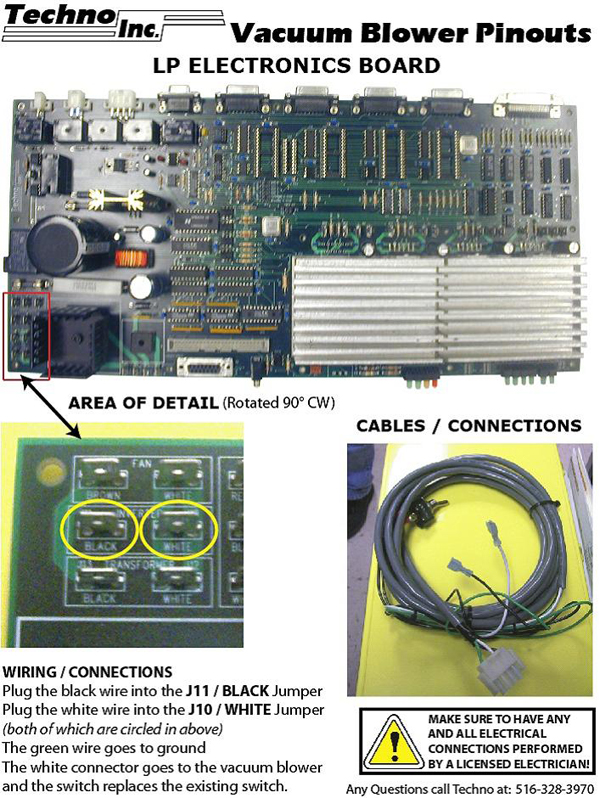
On the controller mainboard, the contacts in the corner are divided into groups:
- Fan
- Inverter
- Transformer
- Power In
- Power switch.
Within each area there is a "Black" and "White". Use either the "Inverter" Black and White OR the "Power In" Black and White. Do not use Power Switch, Fan, or Transformer connections.
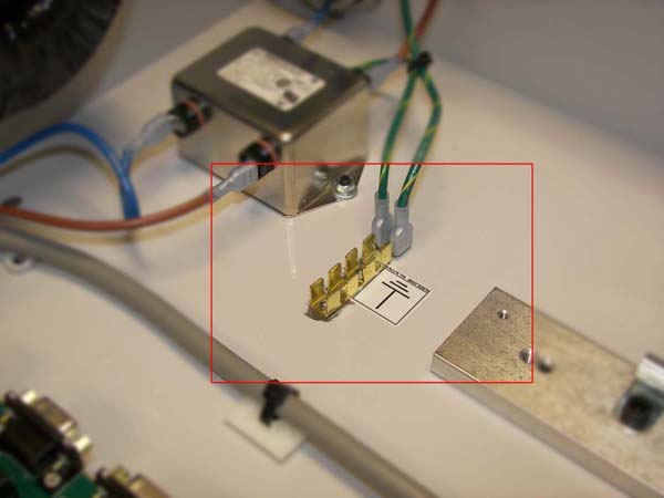
Green wire is ground, usually connects to a header fastened to the box itself
Inverter Setup
Single Phase Operation for Altivar 31 Inverter
drC Menu
- bFR = 60 for 60 Hz (North American operation) or 50 for 50Hz (European operation)
- nCr = Motor current from motor nameplate
- nSP = Motor speed as indicated on motor nameplate
- COS = Power factor as indicated on motor nameplate
- tFr = 60 Hz
SEt Menu
- ACC = 3
- dEC = 3
- LSP = 59
- HSP = 60
- ItH = Current from motor nameplate
FLt Menu
- IPL = No
Auto tune by setting tun to yes in drC menu after all other programming is complete.

