Swapping the motor cables at the control board or back of the control box is a troubleshooting method that is meant to isolate the cause of a problem with the motors.
After swapping the cables:
- If the problem stays on the same axis/motor, that indicates the problem is with that motor or cable.
- If the problem moves to another axis, that means the problem is before the motor cable/motor.
To perform this procedure:
- Lock out power to the machine
- Using a silver marker or tape with writing on it, label the locations and names of all cables you are going to move.
- Take several pictures of the cables and control box with the labels visible. This will assist in troubleshooting and reassembly later.
- Gain access to the inside of the controller or to the back, wherever the connectors lead.
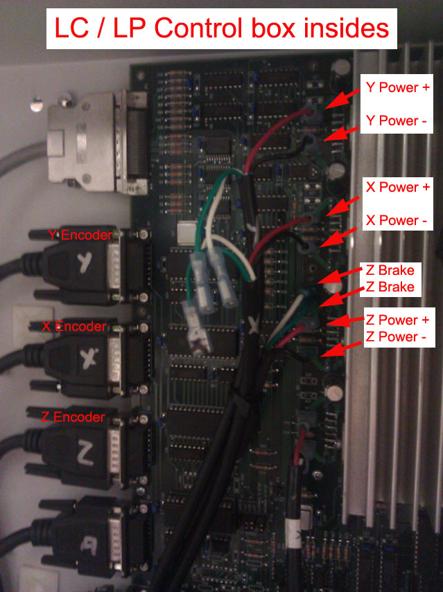
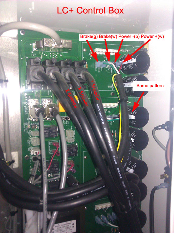
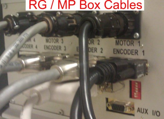
- Locate the motor signal and power cables, which will be in different locations depending on your Controller box
LC / LP Motor/encoder cables
LC+ Motor/encoder cables
Old RG / MP box Motor/encoder cables
- Once you have found the cables, swap the problem axis with another axis by switching BOTH the motor power and encoder signal cables for both motors.
NOTE: Be careful when pulling terminals off the board. NEVER pull a terminal by the wire, always pull by the plastic jacket.
- If you only switch half the cables, or you switch cables randomly between all three axes, the problem will be greatly exacerbated.
- After performing this swap, be cautious when enabling the machine, ready to engage the E-stop at the first sign of trouble.
After performing this procedure, use the result to progress with your troubleshooting by returning to the document that instructed you to perform this procedure in the first place.
Note: If you are going to be working with swapping the Z axis, care must be taken to ensure that the set of cables that will now physically lead to the Z motor have the green and white wires hooked into the proper terminals on the circuit board. This may require you to leave the green and white terminals plugged in while you move the black and red terminals elsewhere.


