| (33 intermediate revisions by 2 users not shown) | |||
| Line 7: | Line 7: | ||
|} | |} | ||
|} | |} | ||
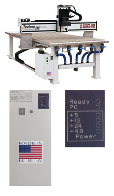
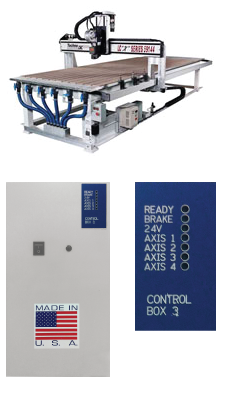
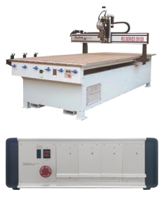
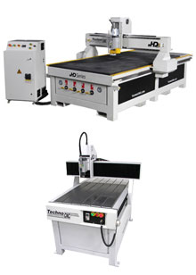
| − | This section is organized by machine / controller type. Though several machines may look similar visually, they are run by very different controllers. Make sure you identify your controller type using the available pictures of machine and controller box. | + | This section is organized by machine / controller type. Though several machines may look similar visually, they are run by very different controllers. Make sure you identify your controller type using the available pictures of machine and controller box. |
| + | |||
| + | Please keep in mind that this section is expanding and is not yet complete. As we move forward, we'll remove the BETA logo from this site. If you find any information that is irrelevant or incorrect, please do not hesitate to let us know by emailing us at support@technorouters.com with the specific page that is incorrect. | ||
{| style="border:0; margin: 0;" width="100%" cellspacing="10" | {| style="border:0; margin: 0;" width="100%" cellspacing="10" | ||
| valign="top" class="mainpage_hubbox" | | | valign="top" class="mainpage_hubbox" | | ||
| Line 13: | Line 15: | ||
<div class="mainpage_boxcontents"> | <div class="mainpage_boxcontents"> | ||
{| style="border: 0; margin: 0;" cellpadding="3" | {| style="border: 0; margin: 0;" cellpadding="3" | ||
| − | | valign="top" | [[File: | + | | valign="top" | [[File:LCSeriesBox.png|left|dsasdasasd|LC Series.]] |
| valign="top" | | | valign="top" | | ||
| Line 21: | Line 23: | ||
* [[Media:0229_LC and Lathe Board-Callouts-Connectors.pdf|Control Board Diagram]] | * [[Media:0229_LC and Lathe Board-Callouts-Connectors.pdf|Control Board Diagram]] | ||
* [[Media:0320_Machine Maintenance Manual-June 2010.pdf|Machine Maintenance Manual]] | * [[Media:0320_Machine Maintenance Manual-June 2010.pdf|Machine Maintenance Manual]] | ||
| + | * [[Media:0439_Techno_CNC_Servo_G-Code_Interface_Manual_-_Build_400.pdf|Techno CNC Interface Manual]] | ||
|} | |} | ||
</div> | </div> | ||
| Line 27: | Line 30: | ||
<div class="mainpage_boxcontents"> | <div class="mainpage_boxcontents"> | ||
{| style="border: 0; margin: 0;" cellpadding="3" | {| style="border: 0; margin: 0;" cellpadding="3" | ||
| − | | valign="top" | [[File: | + | | valign="top" | [[File:LCPlusSeriesBox.png|left|LC+ / LCX.]] |
| valign="top" | | | valign="top" | | ||
| − | The LC + / LCX Controller Series is usually identified by a painted grayish white control box with a black display badge that reads Ready, | + | The LC + / LCX Controller Series is usually identified by a painted grayish white control box with a black display badge that reads Ready, Brake, Axis 0, Axis 1, Axis 2. This kind of controller uses a long (~9") PCI Card. |
* [[Media:0410_LC_Plus_Setup_Instructions_-_051507.pdf|LC+ / LCX Series Basic Setup Instructions]] | * [[Media:0410_LC_Plus_Setup_Instructions_-_051507.pdf|LC+ / LCX Series Basic Setup Instructions]] | ||
* [[Media:0326_Techno_CNC_Router_Reindication_Instructions.pdf|Reindication (Machine Suquaring) Guide]] | * [[Media:0326_Techno_CNC_Router_Reindication_Instructions.pdf|Reindication (Machine Suquaring) Guide]] | ||
* [[Media:0403_MP-HP Servo Controller 3 Motherboard Reference-2009.pdf|Control Board Diagram]] | * [[Media:0403_MP-HP Servo Controller 3 Motherboard Reference-2009.pdf|Control Board Diagram]] | ||
* [[Media:0320_Machine Maintenance Manual-June 2010.pdf|Machine Maintenance Manual]] | * [[Media:0320_Machine Maintenance Manual-June 2010.pdf|Machine Maintenance Manual]] | ||
| + | * [[Media:0439_Techno_CNC_Servo_G-Code_Interface_Manual_-_Build_400.pdf|Techno CNC Interface Manual]] | ||
|} | |} | ||
</div> | </div> | ||
| Line 41: | Line 45: | ||
<div class="mainpage_boxcontents"> | <div class="mainpage_boxcontents"> | ||
{| style="border: 0; margin: 0;" cellpadding="3" | {| style="border: 0; margin: 0;" cellpadding="3" | ||
| − | | valign="top" | [[File: | + | | valign="top" | [[File:RGSeriesBox.png|left|RG Series.]] |
| valign="top" | | | valign="top" | | ||
| − | The RG (Servo Box 1, Servo Box 2) Controller Series is usually identified by a | + | The RG (Servo Box 1, Servo Box 2) Controller Series is usually identified by a aluminum controller box which usually has four doors on its front. Usually at least three of the front doors will have a hole through which a green LED light shines through. This kind of controller uses a long (~9") PCI Card. The RG Series is a discontinued product. |
| − | * [[Media: | + | * [[Media:0439_Techno_CNC_Servo_G-Code_Interface_Manual_-_Build_400.pdf|Techno CNC Interface Manual]] |
| + | * [[Media:0316_RG_Series_Setup_Instructions-377.pdf|RG Series Basic Setup Instructions]] | ||
| + | * [[Media:0330_Readjusting_the_Ball_Nut_.pdf|Readjusting the Ball Nut]] | ||
| + | |||
|} | |} | ||
</div> | </div> | ||
| Line 53: | Line 60: | ||
<div class="mainpage_boxcontents"> | <div class="mainpage_boxcontents"> | ||
{| style="border: 0; margin: 0;" cellpadding="3" | {| style="border: 0; margin: 0;" cellpadding="3" | ||
| − | | valign="top" | [[File:HD_HDMini.jpg|left| | + | | valign="top" | [[File:HD_HDMini.jpg|left|HD Series.]] |
| valign="top" | | | valign="top" | | ||
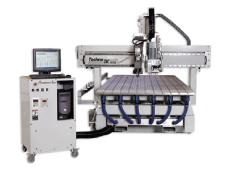
| − | The HD Controller | + | The HD Micro Stepper Controller is identified by a freestanding tower which houses the Controller, Variable Frequency Drive, Amplifiers, Fuses and Breakers. The HD Controller does not require a PC for operation. It is operated using a handheld control pendant with a built-in USB port. The HD Mini Controller is fully self-enclosed but it still uses the same handheld control pendant. |
| − | * [[Media: | + | * [[Media:HD-NCStudio_QuickGuide.pdf|HD Series Quick Setup Guide]] |
| − | * [[Media: | + | * [[Media:Techno-HD-Manual.pdf|HD Series Manual]] |
| − | * [[Media: | + | * [[Media:Techno-HD_Hand-Held_Contoller.pdf|HD Series Hand Held Controller Manual]] |
| − | * [[Media: | + | |
| + | * [[Media:HD_settings.pdf|HD Series Settings]] | ||
| + | * [[Media:Squaring_hd-hds.pdf|HD Series Squaring (Reindication) Guide]] | ||
| + | * [[Media:HD_vacuum_Pump-wiring.pdf|HD Series Vacuum Pump Wiring Guide]] | ||
|} | |} | ||
</div> | </div> | ||
| Line 69: | Line 79: | ||
<div class="mainpage_boxcontents"> | <div class="mainpage_boxcontents"> | ||
{| style="border: 0; margin: 0;" cellpadding="3" | {| style="border: 0; margin: 0;" cellpadding="3" | ||
| − | | valign="top" | [[File: | + | | valign="top" | [[File:HDSSeries.jpg|left|LC Series.]] |
| valign="top" | | | valign="top" | | ||
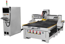
| − | The | + | The HDS Controller is identified by a large freestanding tower which houses the PC, OSAI Controller, Variable Frequency Drive, Amplifiers, Fuses, Breakers, Etc. |
| − | * [[Media: | + | |
| − | * [[Media: | + | * [[Media:0629_Techno-HDS-User-Manual.pdf|HDS Series User Manual]] |
| − | * [[Media: | + | * [[Media:Osai_STARTUP_Procedure_v3.pdf|Startup Procedure]] |
| − | * [[Media: | + | * [[Media:HDS_Quickguide_Flowcharts.pdf|Quick Guide with Flowcharts]] |
| + | * [[Media:HDS_Screen_CalloutsV2.pdf|Main Interface Screen Callouts]] | ||
| + | * [[Media:HDS_Tool_Stand_Tutorial.pdf|Tool Stand Learning Tutorial]] | ||
| + | * [[Media:HDS_Osai_GCODE_GUIDE.pdf|GCODE Guide for Osai Controller]] | ||
|} | |} | ||
</div> | </div> | ||
| + | {| style="border:0; margin: 0;" width="100%" cellspacing="10" | ||
| + | <div class="mainpage_hubtitle">Premium Class Series</div> | ||
| + | <div class="mainpage_boxcontents"> | ||
| + | {| style="border: 0; margin: 0;" cellpadding="3" | ||
| + | | valign="top" | [[File:PremiumSeriesBox.png|left|Premium Series.]] | ||
| + | | valign="top" | | ||
| + | The Premium Series is identified by square black or blue servo motors and a free standing or wheeled controller enclosure. The Premium Series is a discontinued product. | ||
| + | * [[Media:0317_Premium Class Setup Instructions-377.pdf|Premium Class Basic Setup Instructions]] | ||
| + | * [[Media:0319_Premium Class Lubrication Instructions.pdf|Premium Class Lubrication Guide]] | ||
| + | * [[Media:0320_Machine Maintenance Manual-June 2010.pdf|General Machine Maintenance Guide]] | ||
| + | * [[Media:0439_Techno_CNC_Servo_G-Code_Interface_Manual_-_Build_400.pdf|Techno CNC Interface Manual]] | ||
| + | |} | ||
| − | + | </div> | |
| − | + | ||
| − | + | ||
| − | + | ||
{| style="border:0; margin: 0;" width="100%" cellspacing="10" | {| style="border:0; margin: 0;" width="100%" cellspacing="10" | ||
| − | + | <div class="mainpage_hubtitle">Servo DaVinci Series</div> | |
| − | <div class="mainpage_hubtitle"> | + | |
<div class="mainpage_boxcontents"> | <div class="mainpage_boxcontents"> | ||
{| style="border: 0; margin: 0;" cellpadding="3" | {| style="border: 0; margin: 0;" cellpadding="3" | ||
| − | | valign="top" | | + | | valign="top" | [[File:ServoDavinciSeriesBox.png|left|Servo DaVinci Series.]] |
| valign="top" | | | valign="top" | | ||
| − | * [[ | + | |
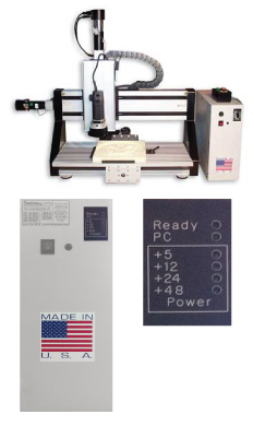
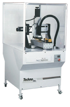
| − | * [[ | + | The Servo DaVinici series is identified by a controller enclosure whose status lights are Ready, PC, +5, +25, +48 and round servo motors. Servo DaVinci machines are sometimes in an enclosure but have been made in tabletop styles. |
| − | * [[ | + | * [[Media:0439_Techno_CNC_Servo_G-Code_Interface_Manual_-_Build_400.pdf|Techno CNC Interface Manual]] |
| − | * [[ | + | * [[Media:0326_Techno_CNC_Router_Reindication_Instructions.pdf|Reindication (Machine Suquaring) Guide]] |
| + | * [[Media:0229_LC and Lathe Board-Callouts-Connectors.pdf|Control Board Diagram]] | ||
| + | * [[Media:0320_Machine Maintenance Manual-June 2010.pdf|Machine Maintenance Manual]] | ||
|} | |} | ||
| − | |||
| − | | | + | |
| − | <div class="mainpage_hubtitle"> | + | </div> |
| + | {| style="border:0; margin: 0;" width="100%" cellspacing="10" | ||
| + | <div class="mainpage_hubtitle">Stepper DaVinci Series</div> | ||
<div class="mainpage_boxcontents"> | <div class="mainpage_boxcontents"> | ||
{| style="border: 0; margin: 0;" cellpadding="3" | {| style="border: 0; margin: 0;" cellpadding="3" | ||
| − | | valign="top" | | + | | valign="top" | [[File:StepperDavinciSeriesBox.png|left|Servo DaVinci Series.]] |
| + | | valign="top" | | ||
| + | |||
| + | The Stepper DaVinici series is identified by a controller housed in the body of the machine that has an external LED status light indicator and square black servo motors with a knob at the top.Stepper DaVinci machines are sometimes in an enclosure but have been made in tabletop styles. | ||
| + | * [[Media:0011_Router Setup for DaVinci.pdf|Stepper DaVinci Setup Guide]] | ||
| + | * [[Media:0061_Educational DaVinci Setup.pdf|Education Series Stepper DaVinci Setup Guide]] | ||
| + | * [[Media:0049_GCODE STEPPER DAVINCI.pdf|Stepper DaVinci GCODE Guide]] | ||
| + | * [[Media:0224_Stepper Davinci Trouble Shooting Guide.pdf|Stepper DaVinci Troubleshoting Guide]] | ||
| + | * [[Media:0260_Davinci_Spare_Parts_List.pdf|Stepper DaVinci Spare Parts List]] | ||
| + | |||
| + | |||
| + | |||
| + | |||
| − | |||
|} | |} | ||
| − | |||
| − | | | + | |
| − | <div class="mainpage_hubtitle"> | + | |
| + | |||
| + | |||
| + | |||
| + | {| style="border:0; margin: 0;" width="100%" cellspacing="10" | ||
| + | <div class="mainpage_hubtitle">Inverters / Variable Frequency Drives</div> | ||
<div class="mainpage_boxcontents"> | <div class="mainpage_boxcontents"> | ||
{| style="border: 0; margin: 0;" cellpadding="3" | {| style="border: 0; margin: 0;" cellpadding="3" | ||
| + | | valign="top" | [[File:invertertypes.jpg|left|Inverters / Variable Frequency Drives]] | ||
| valign="top" | | | valign="top" | | ||
| − | |||
| − | |||
| − | |||
| − | |||
| − | |||
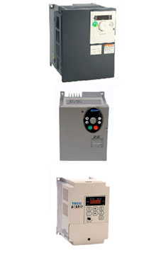
| − | + | Inverters (Variable Frequency Drives) are responsible for powering the spindle and sometimes a vacuum pump. Over the years, Techno has used Motortronics, Telemechanique and Schneider Electric brands. | |
| + | * [[Media:UM312_en.pdf|Altivar 312 General Programming & Troubleshooting Guide (Telemechanique / Schneider Electric)]] | ||
| − | |||
| − | |||
| − | |||
| − | |||
| − | |||
| + | |} | ||
| + | </div> | ||
Latest revision as of 15:28, 28 August 2013
|
This section is organized by machine / controller type. Though several machines may look similar visually, they are run by very different controllers. Make sure you identify your controller type using the available pictures of machine and controller box.
Please keep in mind that this section is expanding and is not yet complete. As we move forward, we'll remove the BETA logo from this site. If you find any information that is irrelevant or incorrect, please do not hesitate to let us know by emailing us at support@technorouters.com with the specific page that is incorrect.
|
LC Series
|
